The 3D simulator
hp-sim-3d is the current application. It combines the 3D machine model, physics, controls, diagnostics, and visualization in the browser.
Open hp-sim-3dHangprinter Project / Simulation
hp-sim is a physics simulation used to develop Hangprinter machines and their control software.
It brings machine geometry, cable mechanics, spool behavior, firmware, and calibration into repeatable experiments.

In one sentence: hp-sim runs a Hangprinter machine model and its control software together so that the same experiment can be repeated and compared.
THE MACHINE
Hangprinter is an open-source cable-driven parallel robot. It moves a tool through a workspace using synchronized lines instead of a conventional gantry.
This makes large workspaces possible with relatively little fixed structure. It also means that the parts of the machine are closely connected. A change to one line, spool, anchor, motor, or control setting can affect the rest of the system.
Cable-driven parallel robots have many strengths, but the coupled mechanics are challenging to control. Physical experiments are slow to reset and difficult to compare.
THE SIMULATION
A useful Hangprinter simulation must include more than the path of the tool. It must also include the machine that creates that path.
hp-sim models the physical machine together with its motion commands. This makes it possible to study whether an observed behavior comes from geometry, cable forces, spool buildup, firmware, or calibration.
A proposed change can first be tested under controlled conditions. The inputs, measured outputs, and starting state can stay the same between runs. The change can then be judged against a baseline.
Each stage adds one part of the real system. Together they form a repeatable simulation run.
Define the anchors, moving parts, masses, spools, lines, and other physical properties.
Use the same G-code and firmware behavior that will control a physical machine.
Calculate how the motors, spools, lines, and rigid bodies affect one another over time.
Record the tool path and diagnostics, then repeat the experiment after changing one part of the system.
RefWinch, RefRig, and full-size Hangprinters address different physical scales. hp-sim provides a common place to test machine models, control software, and calibration methods used across them.
A reference actuator for controlling one line length accurately.
A compact reference machine for testing several winches together.
The larger cable-driven machine and the project that connects the work.
Tests machine behavior, firmware, and calibration before or alongside work on physical hardware.
HP-SIM-3D
hp-sim-3d is the actively developed application. It models rigid assemblies, driven spools, cable paths, and machine motion in a 3D workspace.
The move from 2D to 3D is complete. Full inertia tensors, three-dimensional rigid-body motion, rotational degrees of freedom, and generalized 3D joints are implemented. Basic spool buildup is also implemented by winding line in layers.
Spool rotors currently use a specialized one-axis model that fits the required motion. A generic hinge can be added later if bearing reactions or off-axis rotor behavior need to be studied, but it is not a prerequisite for the present simulator.
Read the 3D implementation notes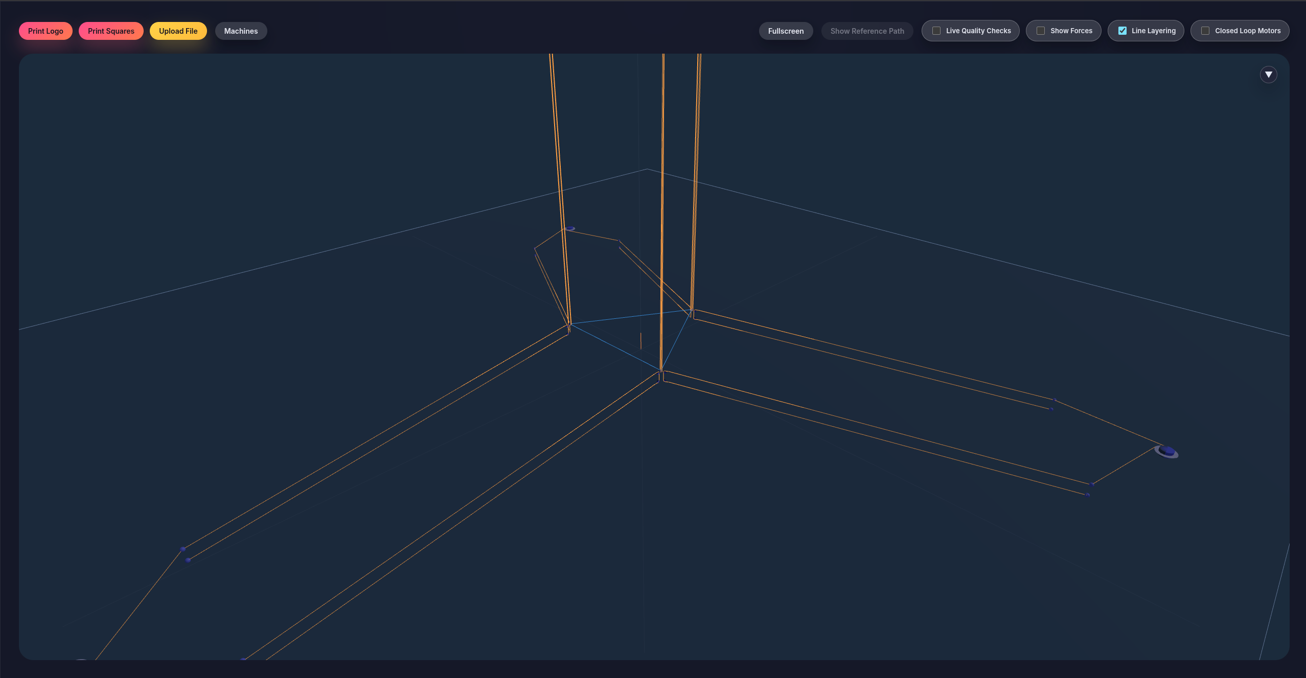
The repository contains the active 3D application and the supporting work needed to connect physics, firmware, calibration, and tests.
hp-sim-3d is the current application. It combines the 3D machine model, physics, controls, diagnostics, and visualization in the browser.
Open hp-sim-3dKlipper and a host build of ReprapFirmware can generate the motor commands. This lets experiments include real control software instead of an approximation of it.
Read the firmware notesThe autocal tools run calibration procedures against simulated machines. They can test geometry fitting, force settings, and measurement strategies before physical trials.
Read the calibration notesThe repository also contains the 2D simulator, related JavaScript and Python physics work, tests, and an optional Warp implementation for CPU or GPU experiments.
Open the 2D simulatorCurrent work builds on the completed 3D physics foundation. The focus is shifting toward physical HP5 design, verification, and larger experiment workflows.
The latest discussion of spool buildup is in the June 2026 post on winch precision and design findings. Read the post
The 3D application is the best place to see the current work. The repository contains implementation details, tests, and development history.